Step 1: Hardware assembly
Welcome to the tutorial for assembling the senseBox:home
Note: Since December 2020, a new acrylic case has been used. Only the first step differs from the previous assembly. All other steps can be carried out analogously to the old case.
Since the senseBox is a modular kit, individual steps for sensors may vary or even be skipped in your case.
Inserting the MCU into the Case
In the first step, the MCU is inserted into the case. The system has been slightly revised over time, so a new mounting system has been used since December 2020.
senseBox:home from December 2020
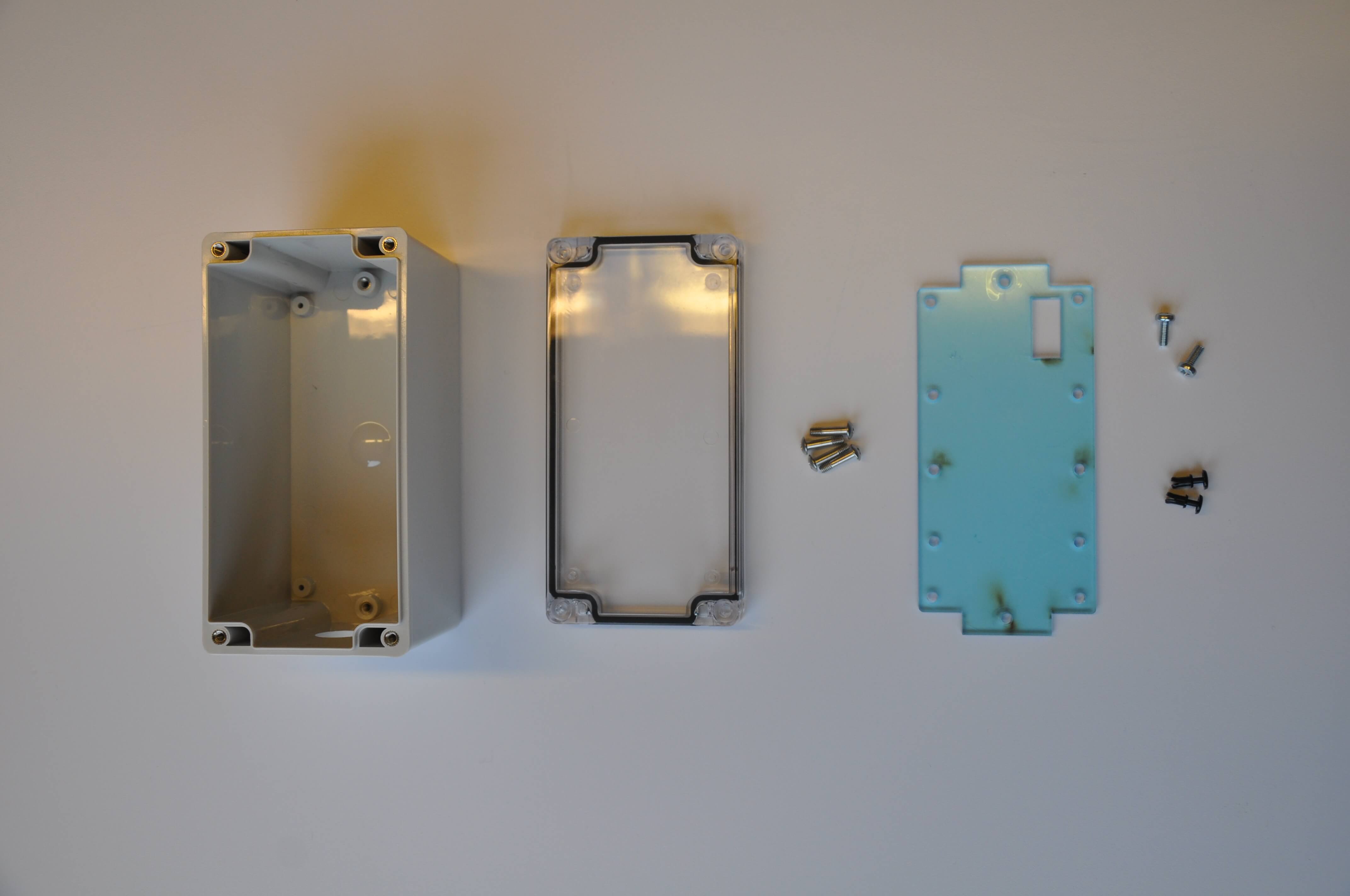
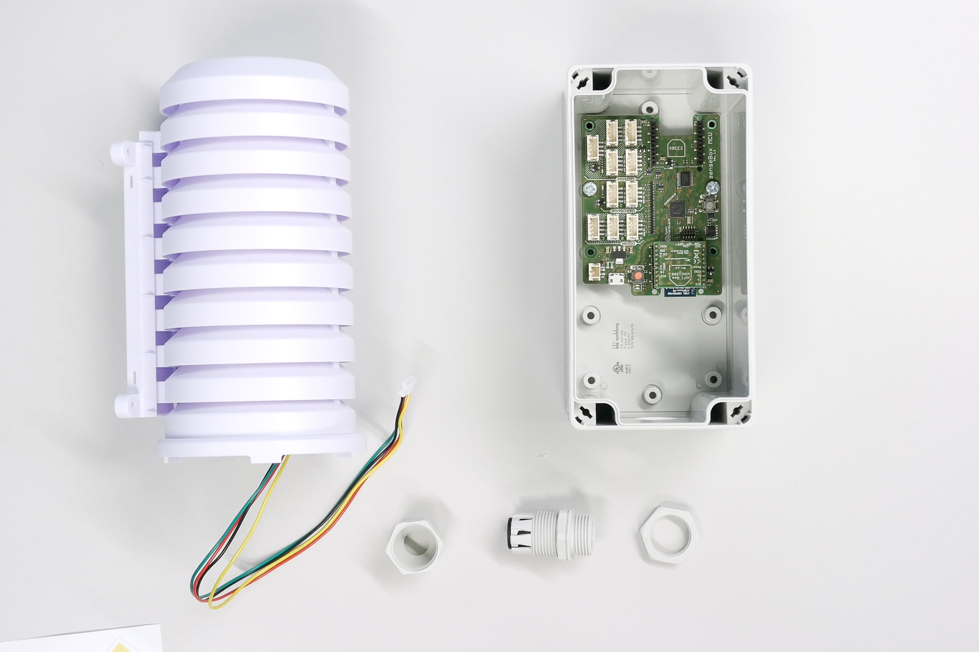
senseBoxes purchased since December 2020 are equipped with a new case. The assembly differs only slightly in the first steps from the old version. First, we get an overview of the available components.
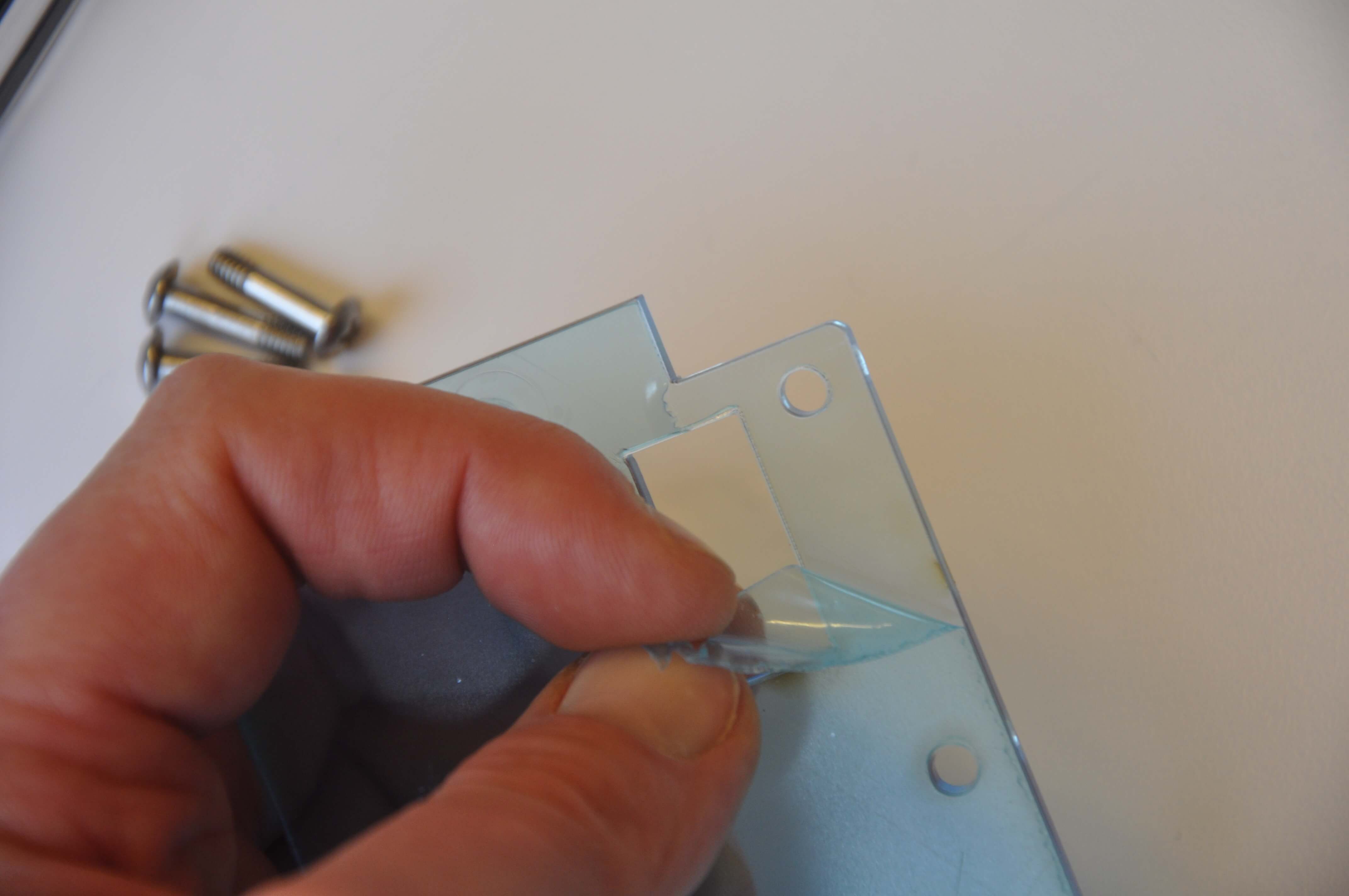
The protective film can now be removed from the acrylic plate.
Now screw the acrylic plate into the case. Make sure that the opening for the USB port aligns with the opening of the case. After that, you can use the black screws to attach the senseBox MCU to the acrylic plate. Again, ensure that the USB port is aligned with the opening of the case.

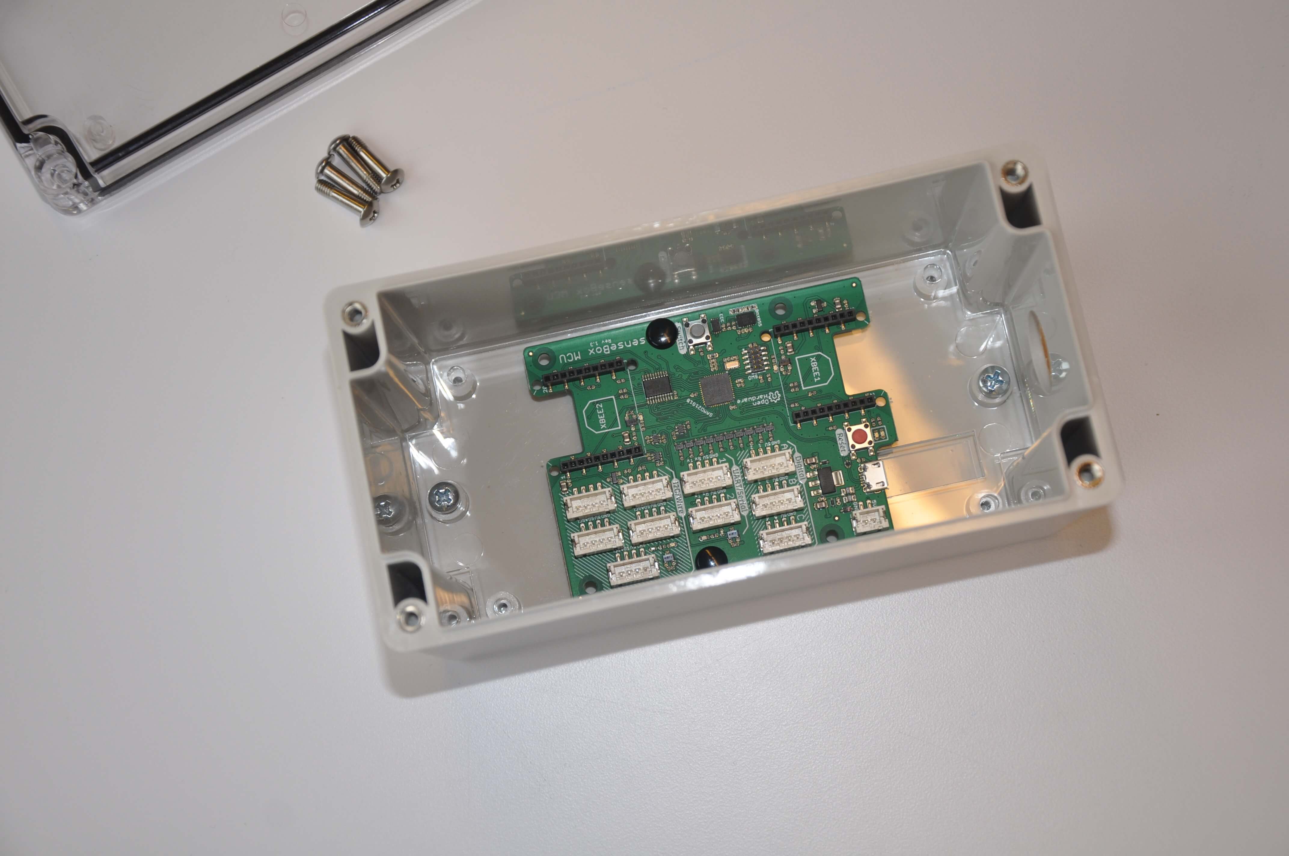
The following steps can be carried out analogously to the old case/mounting system.
senseBox:home until November 2020
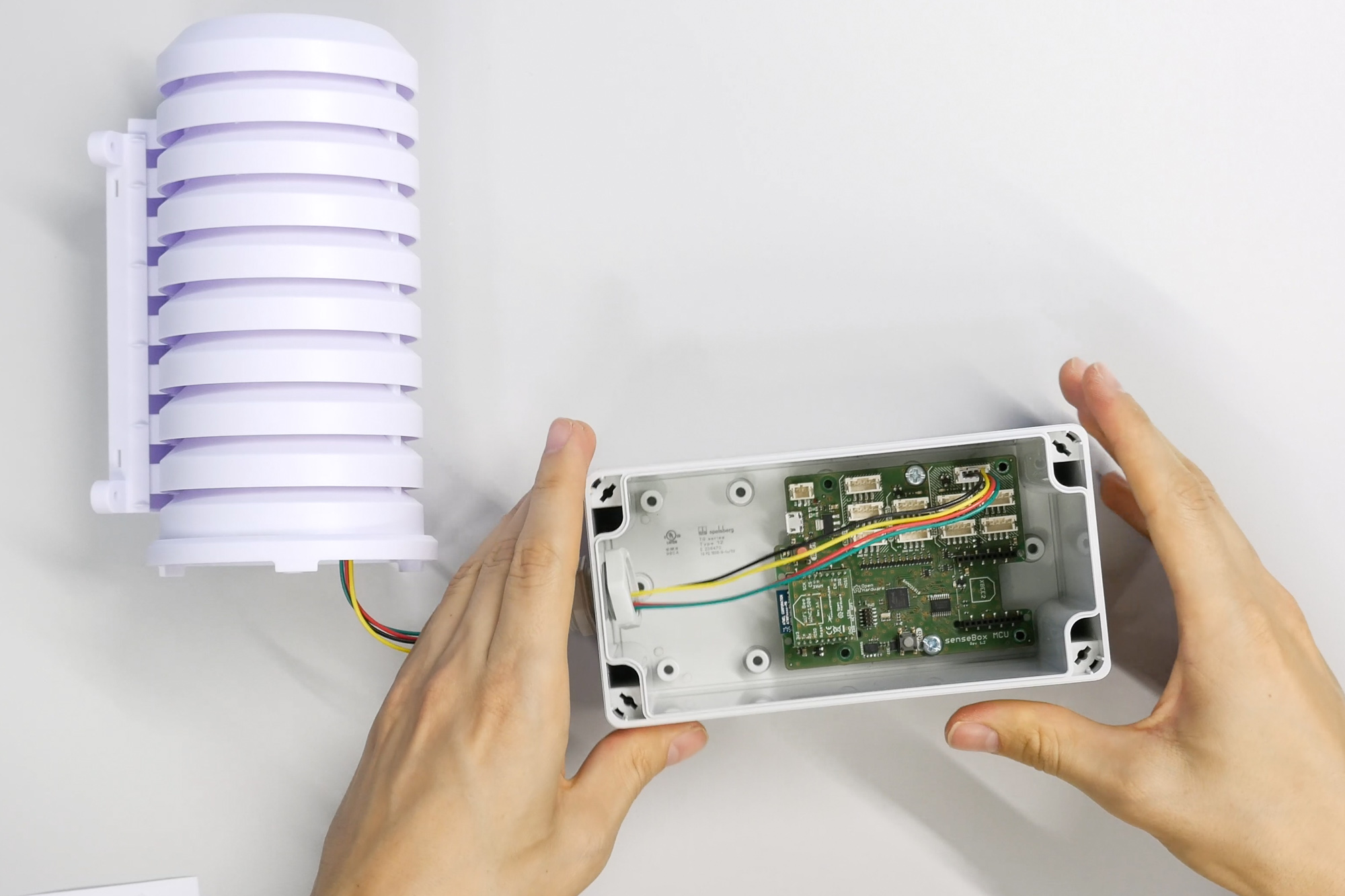
First, we will show how to insert the microcontroller into the case.
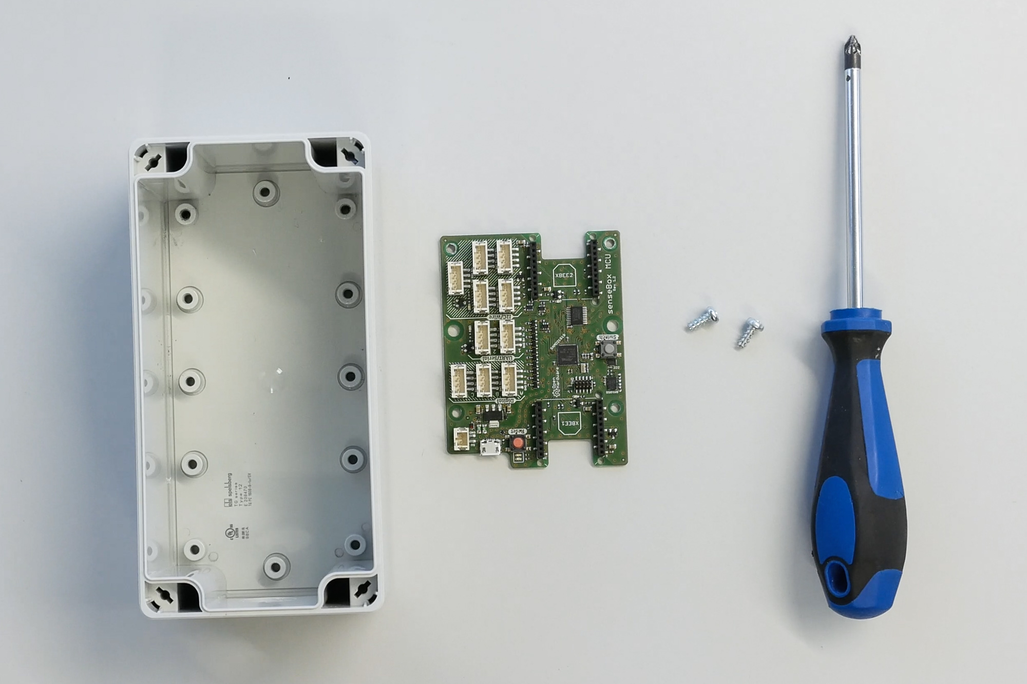
Take the case and align it with the drilled hole facing downwards. Place the green senseBox microcontroller on the opposite side so that the red reset button and the USB port are facing forward.
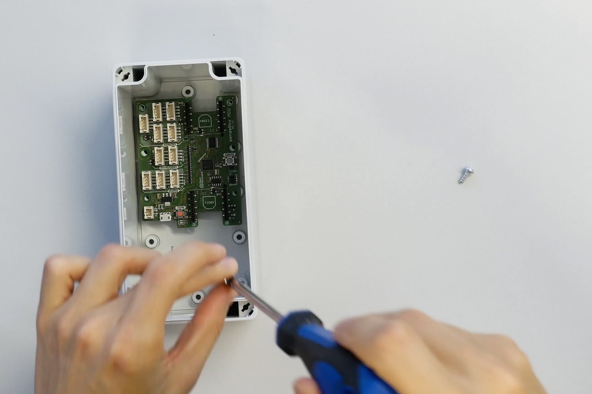
Now, take the two smaller screws included and attach the PCB to the housing through the middle mounting holes.
If the PCB has some play, it’s not a problem.
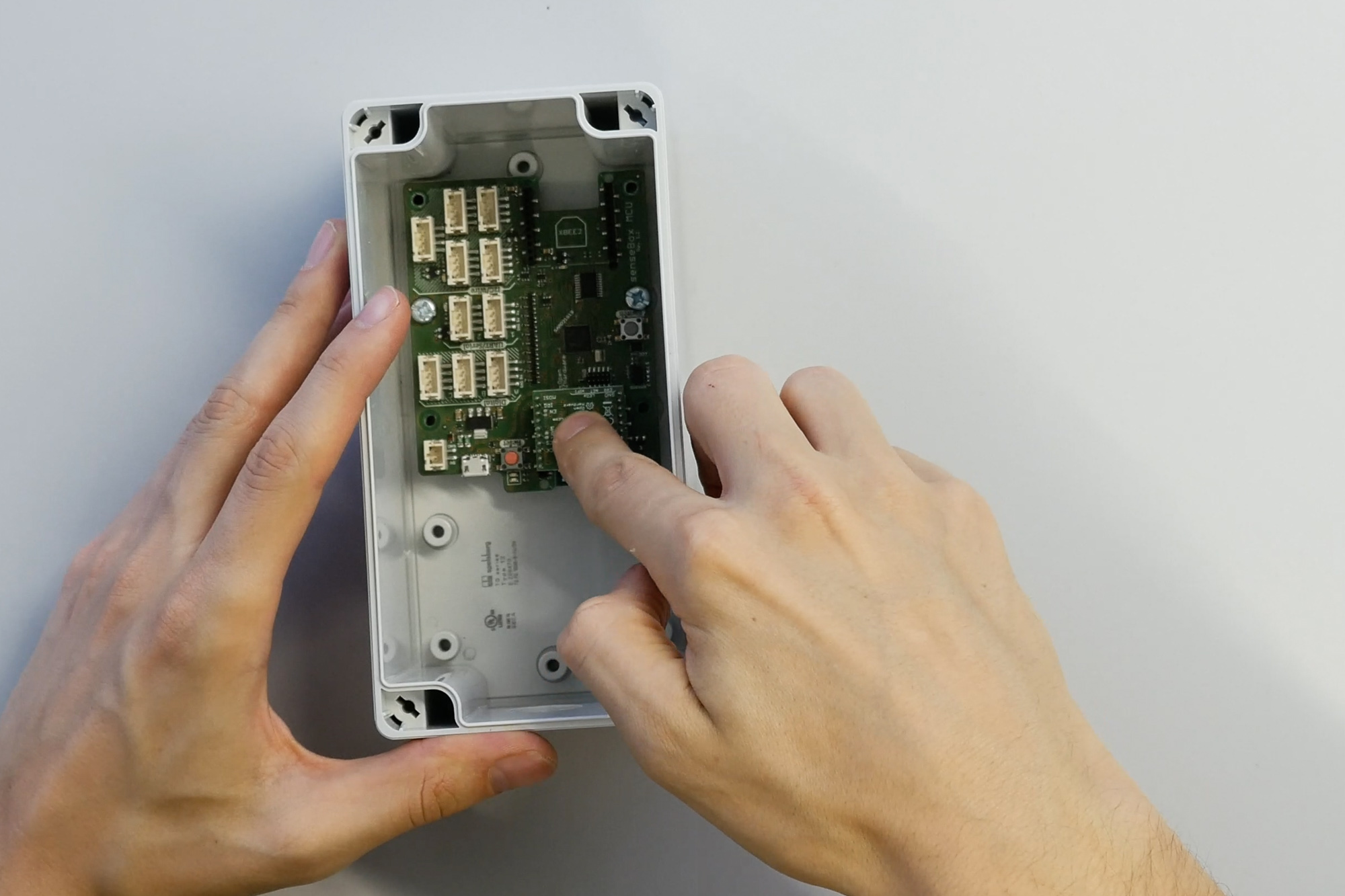
Attaching the WiFi-Bee
Next, we’ll demonstrate how to attach the WiFi-Bee.
Each Bee module includes a marking that indicates the correct orientation.
If you have a different data transmission module, such as LAN or LoRaWAN, the attachment process is the same.

The WiFi-Bee is mounted on XBee Port 1 and carefully pressed into the socket so that all the Bee's pins are securely inserted.
Assembling the Radiation Shield Housing
Now, we’ll show how to assemble the radiation shield housing, where the temperature and humidity sensor will be installed.
The radiation shield includes some mounting parts for attaching it externally, but we won’t need them initially.
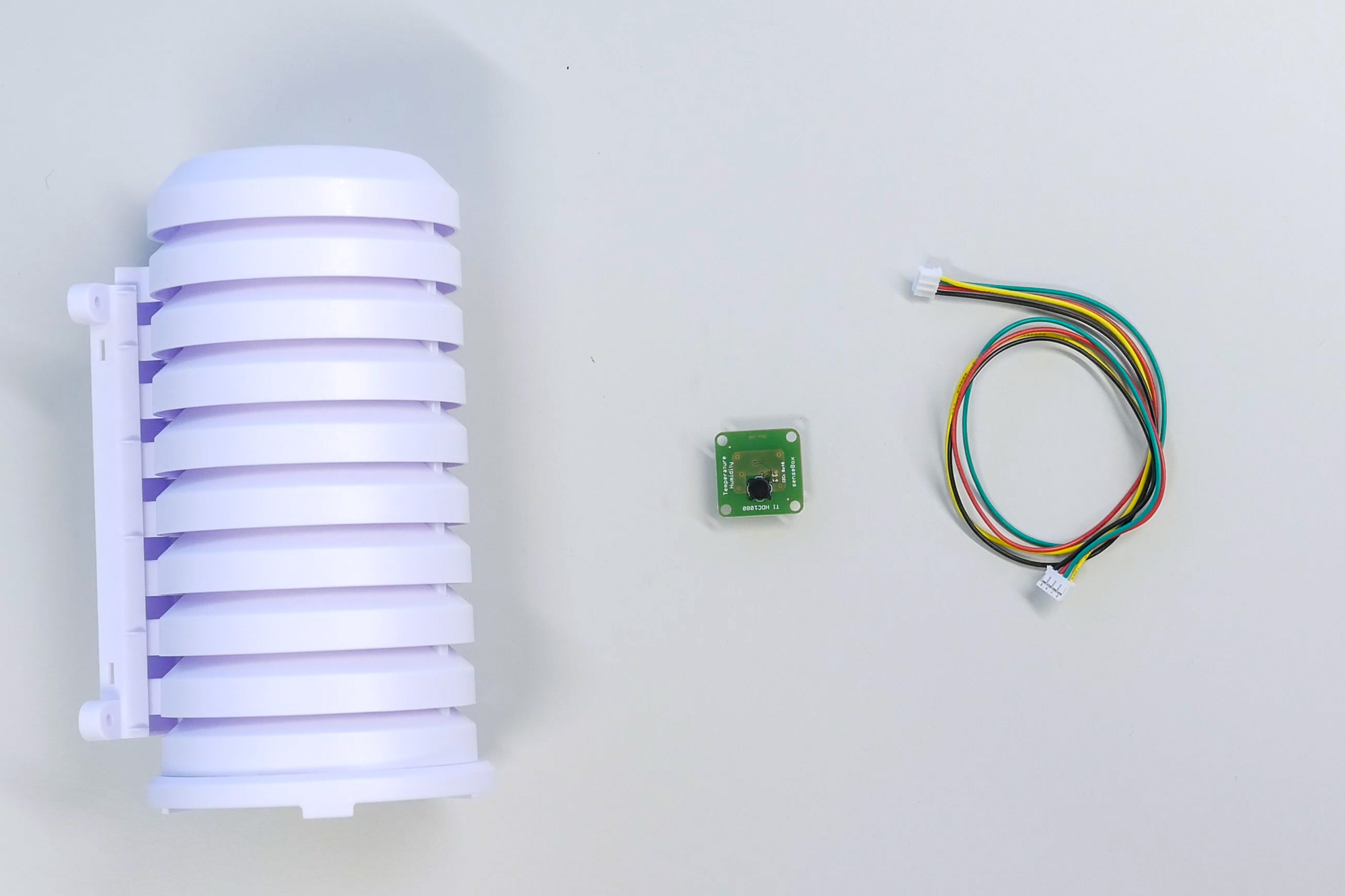
First, thread a long senseBox cable through the opening at the base of the radiation shield and connect it to the temperature and humidity sensor inside.
The sensor can also be secured to the stand with tape or a cable tie.
The radiation shield housing ensures good air circulation and protects the sensor from weather conditions.
Now, assemble the radiation shield housing. Later, the sensor will be connected to the senseBox microcontroller.
Assembling the Particulate Matter Sensor
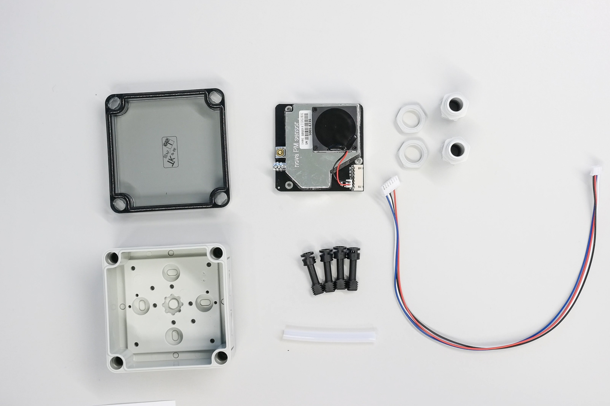
Next, we’ll demonstrate how to assemble the particulate matter sensor.
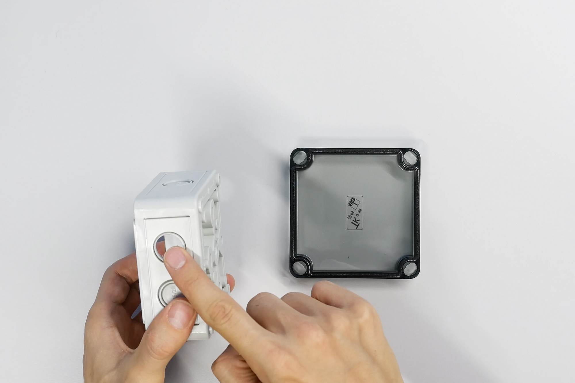
The housing for the sensor must have openings for cables and air intake.
These openings should be on opposite sides with two predefined breakpoints each.
For safety reasons, we recommend drilling these openings.
Theoretically, you can also punch them out at the breakpoints with a blunt object.
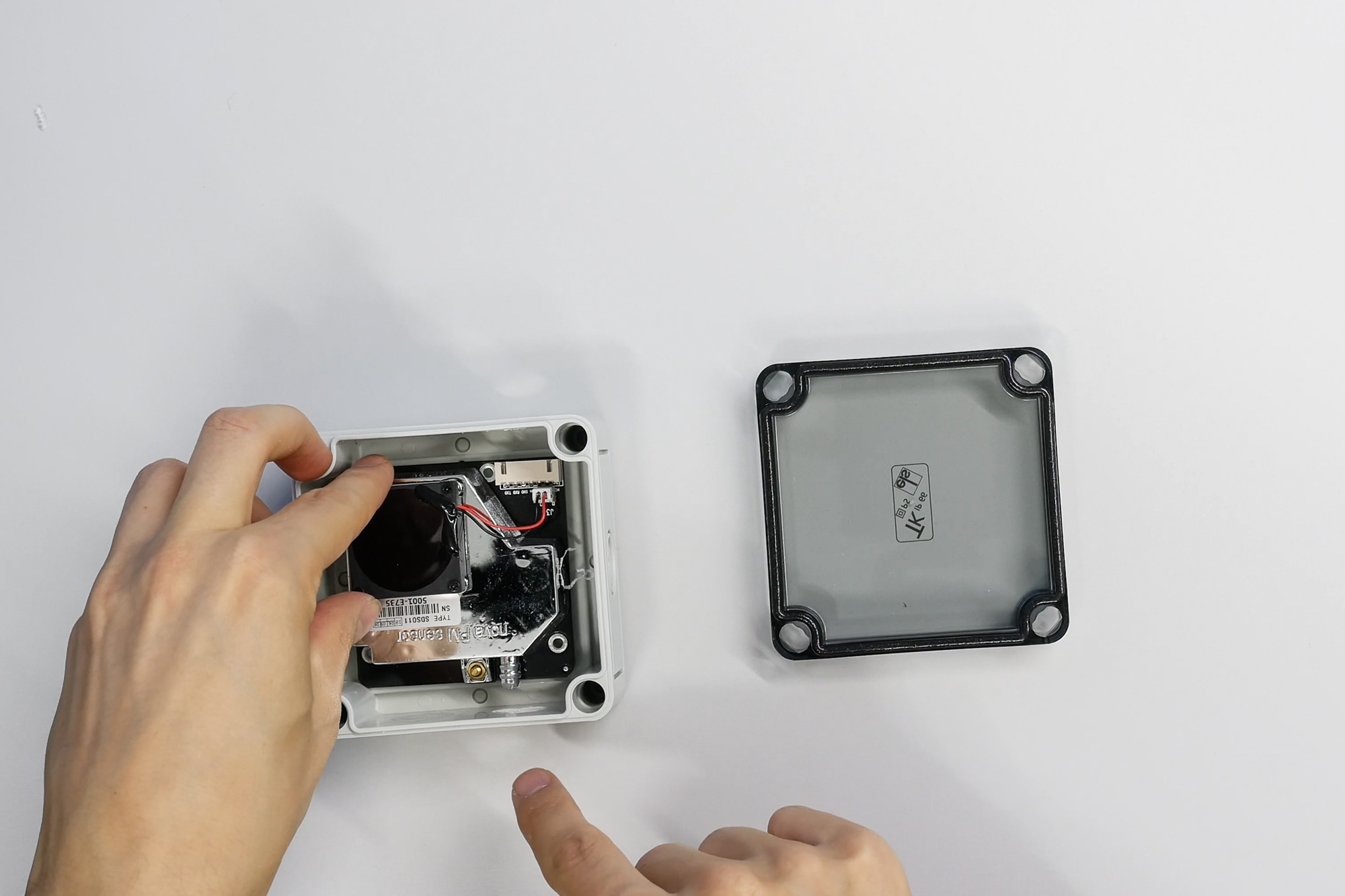
Next, place the particulate matter sensor inside the housing,
ensuring that the cable connection and air intake nozzle align with the newly created openings.
The cable for the particulate matter sensor has a different color and should be connected to the larger connector on the sensor.
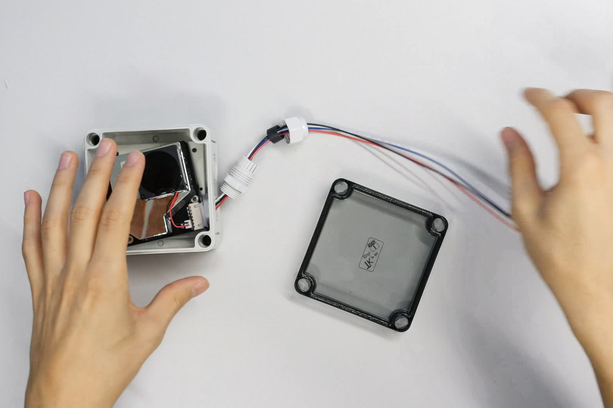
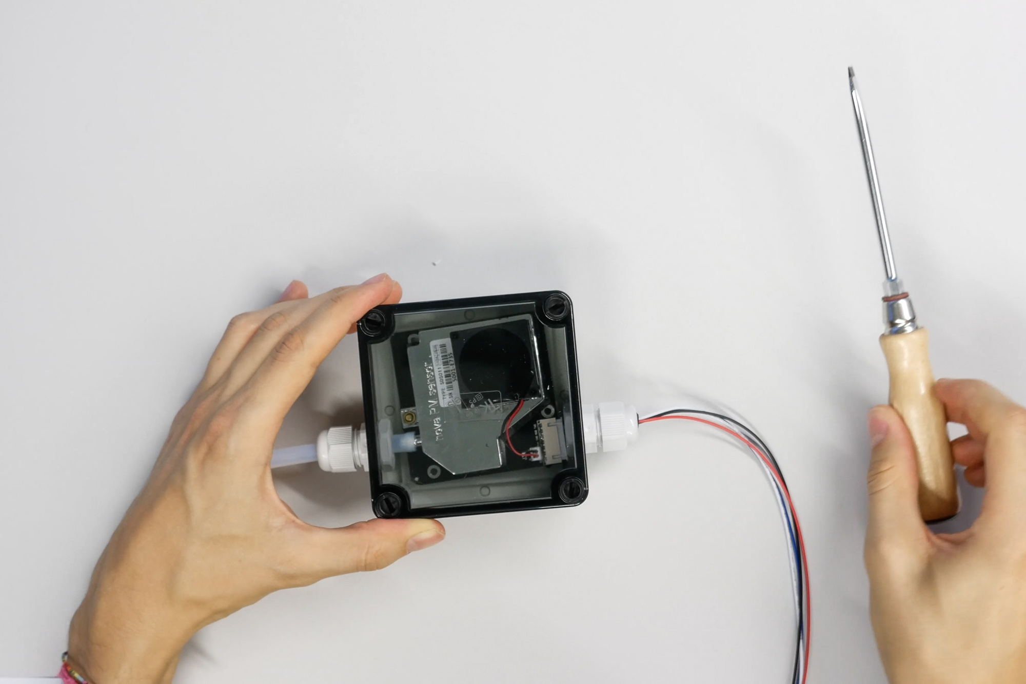
Then, attach the cable glands.
Disassemble the cable gland and arrange the individual parts in the correct order. Then screw them back together securely.
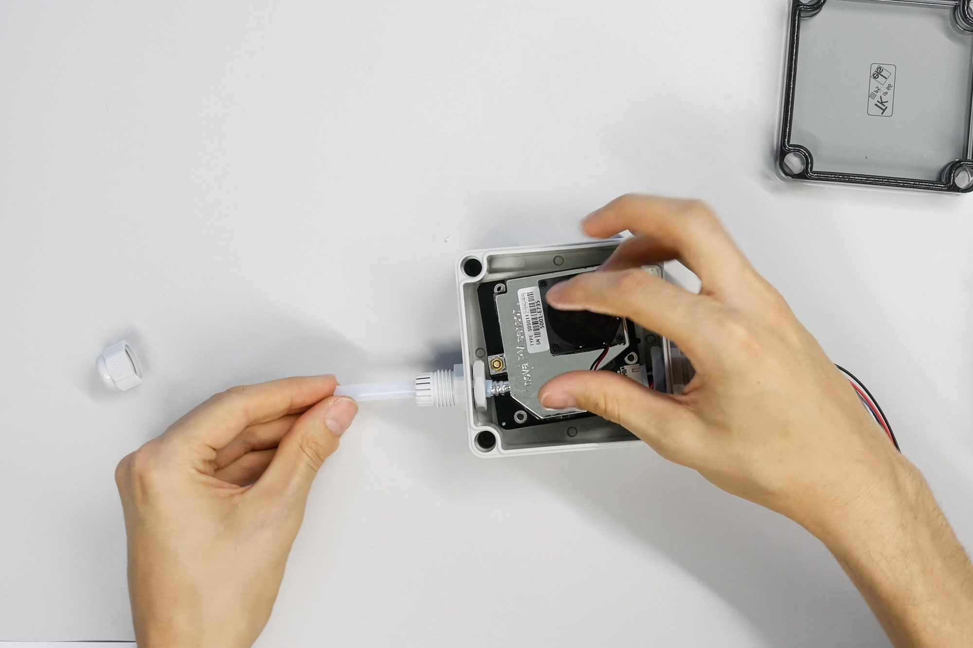
On the other side of the sensor, attach the hose to the air intake nozzle.
The air intake nozzle now comes with a filter. This filter prevents coarse dirt and insects from entering the sensor.
Use a cable gland to seal the hose. After arranging everything correctly, a bit of pressure is required to attach the hose to the nozzle.
Finally, put on the lid, and the particulate matter sensor is ready.
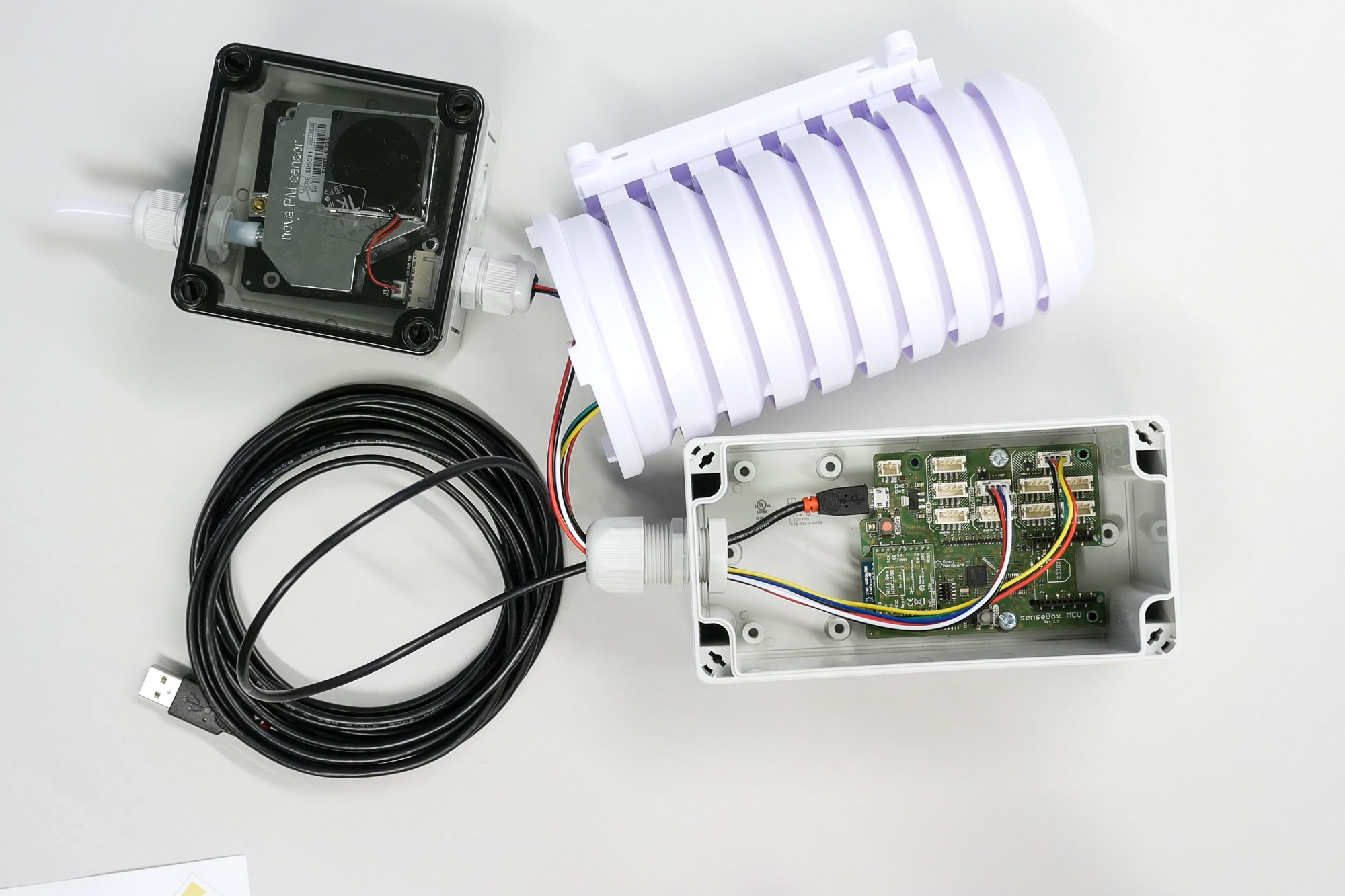
Connecting External Sensors to the MCU
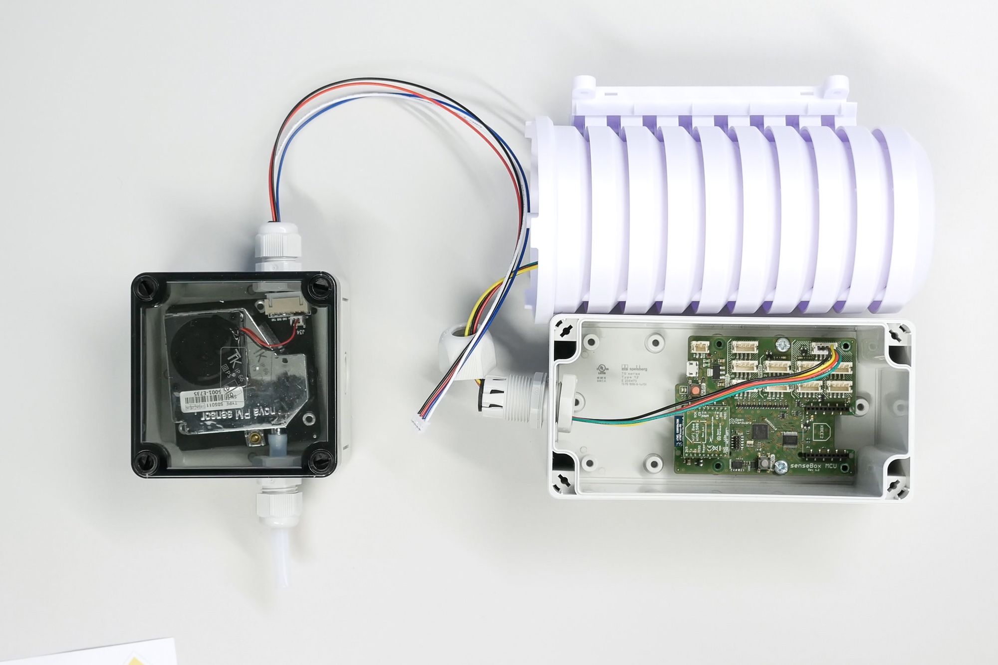
The external sensors, including the temperature and humidity sensor and the particulate matter sensor, are now connected to the MCU.
First, take the cable from the radiation shield and thread it through the last cable gland into the housing.
Connect the cable to one of the slots labeled I2C/Wire.
Next, take the cable from the particulate matter sensor and thread it through the cable gland.
This cable goes into one of the slots labeled UART/Serial.
Connecting the USB Cable
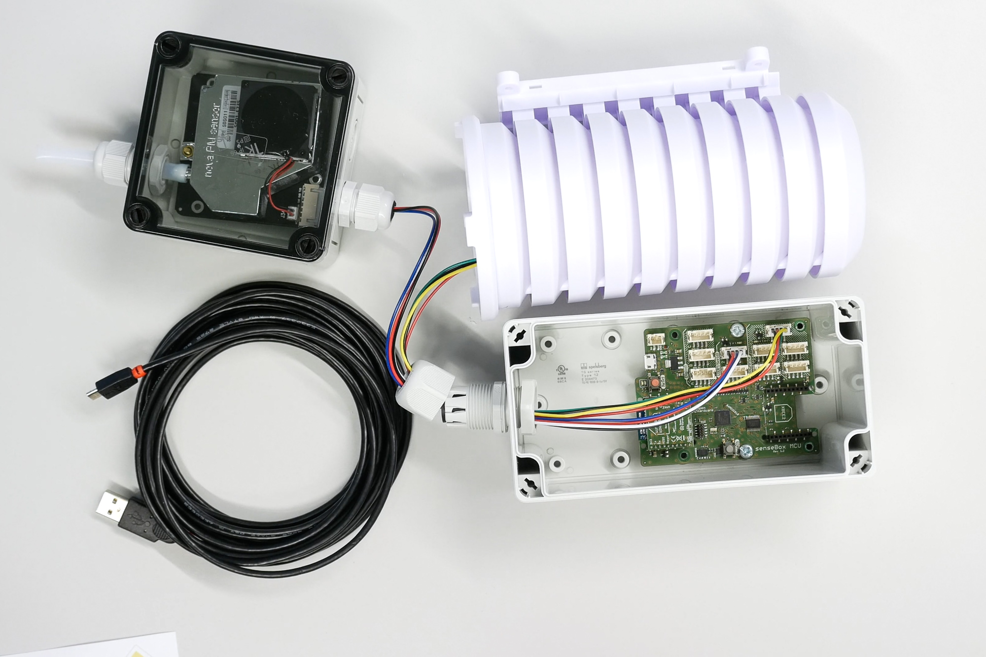
Finally, connect the mini-USB cable, which is used to program the microcontroller and power the senseBox during operation.
Please note that the mini-USB port is sensitive and exposed to the leverage effect of the cable.
Therefore, avoid pulling on the USB cable.
Connecting Internal Sensors to the MCU
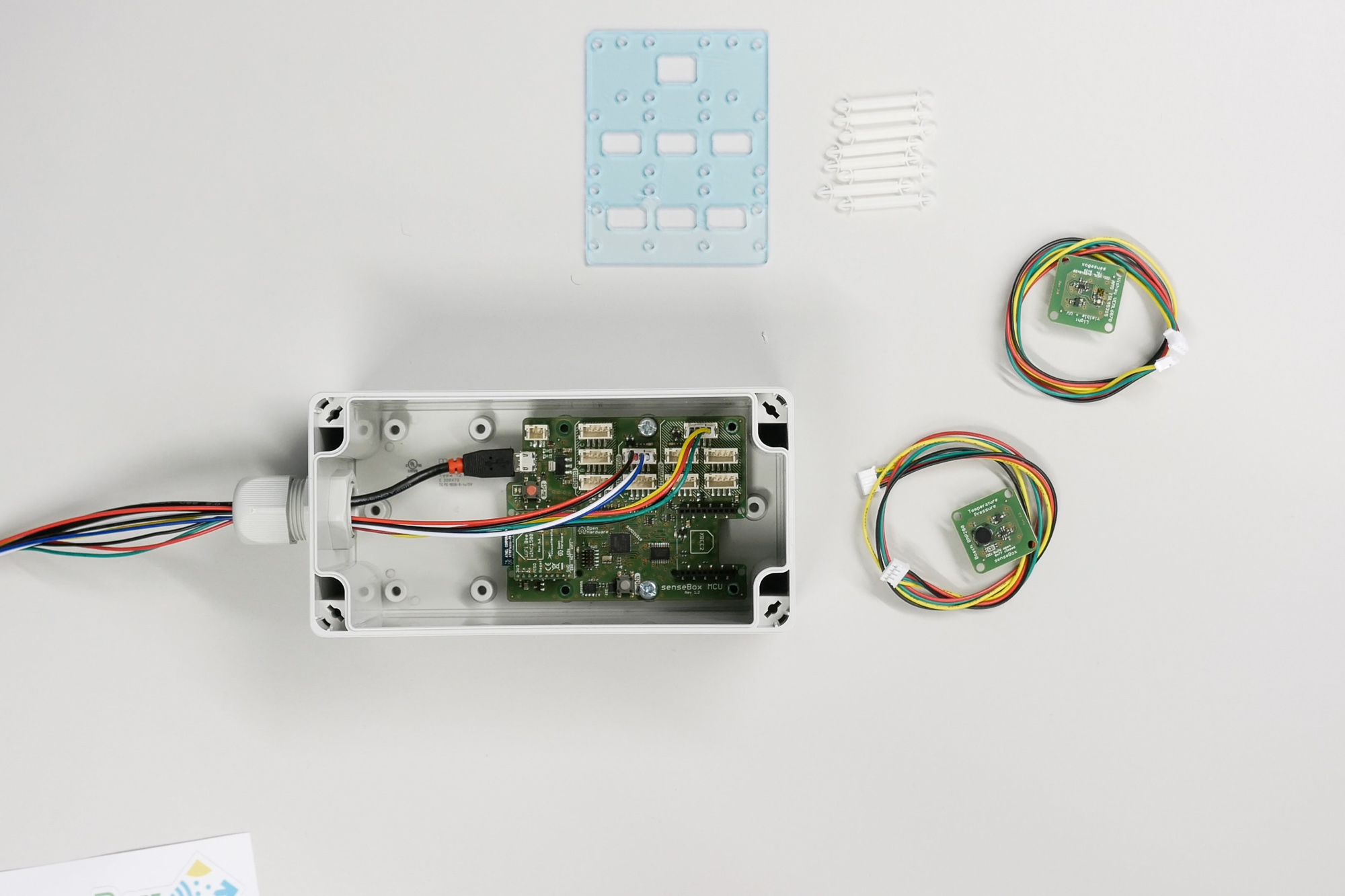
After connecting the external sensors, the remaining sensors inside the housing are installed.
First, assemble a mounting level. Insert four spacers into the outer holes of the microcontroller.
The spacers have a snap mechanism. If you need to remove them, press lightly on the head instead of forcing them out.
Next, connect two senseBox cables to the I2C/Wire slots for the air pressure sensor and light sensor.
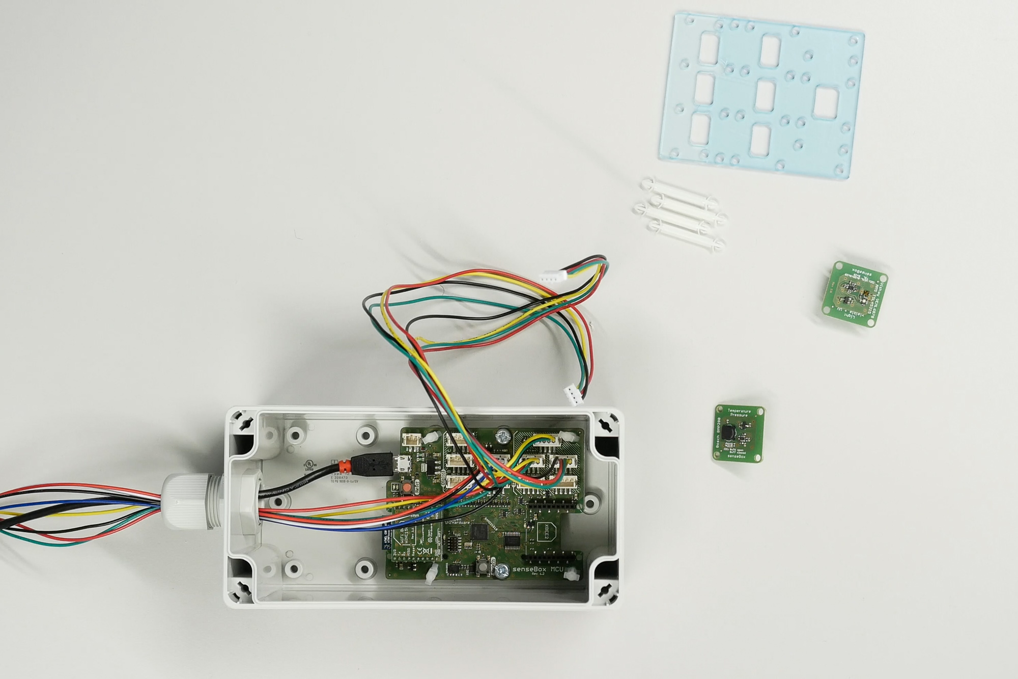
Thread the cables through the middle openings of the mounting plate.
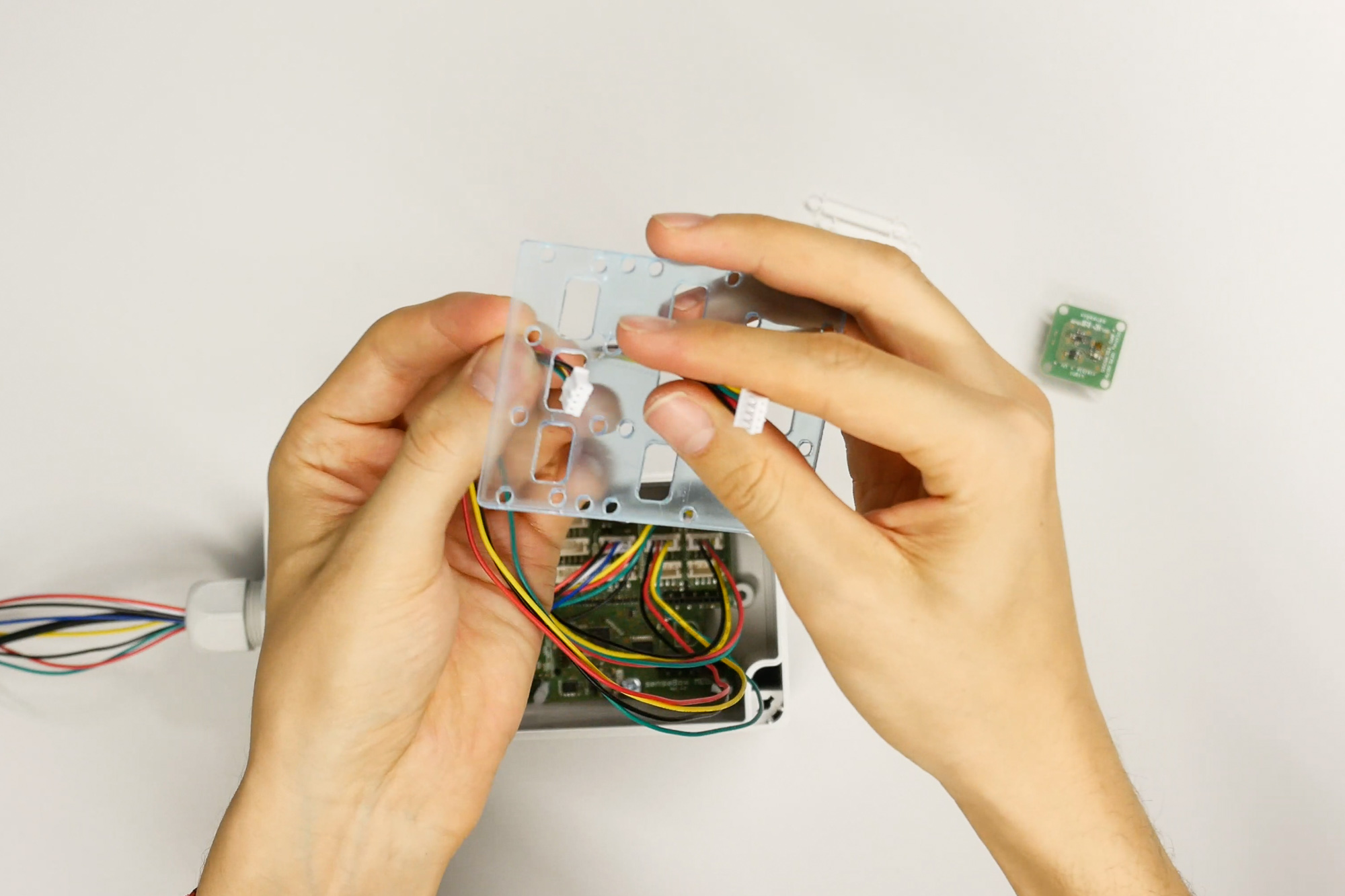
Then, press the mounting plate onto the spacers and connect the cables to the sensors.
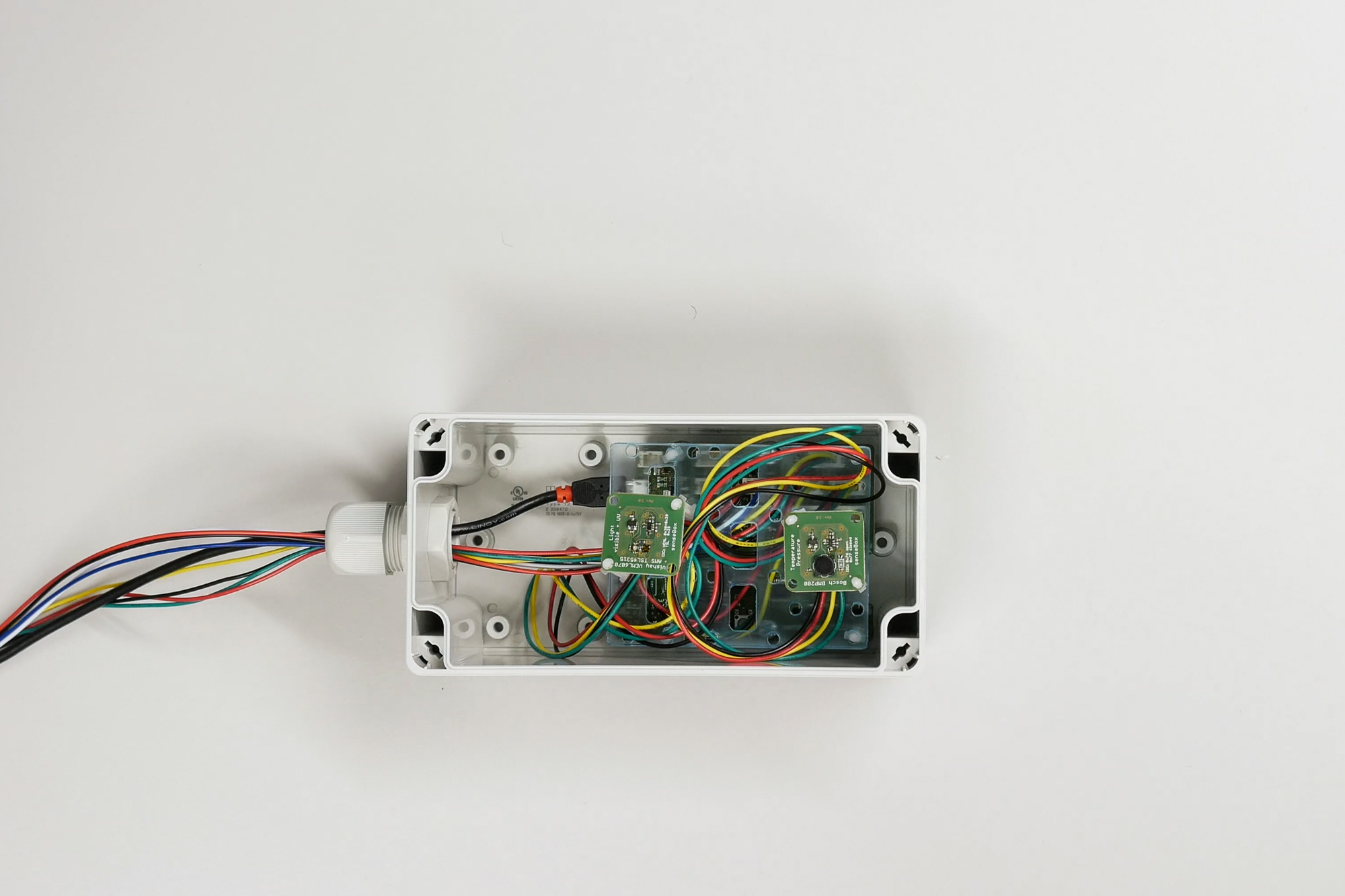
Equip each sensor with two spacers and attach them to the mounting plate.
If you have chosen a light sensor, place it as centrally as possible in the housing to obtain accurate measurements.
The air pressure sensor can be installed in the outer slot.
Finally, secure the lid with screws and place a silica gel packet inside the housing for additional moisture protection.
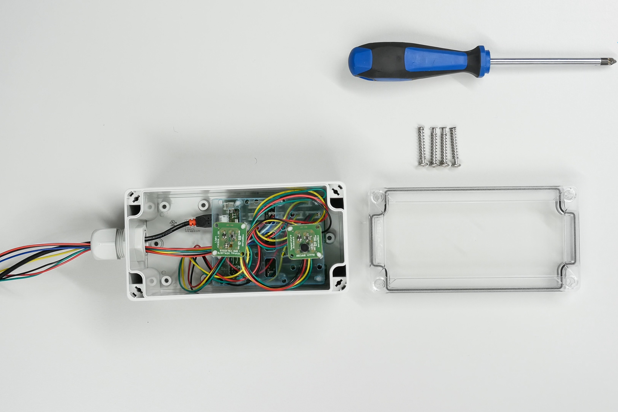
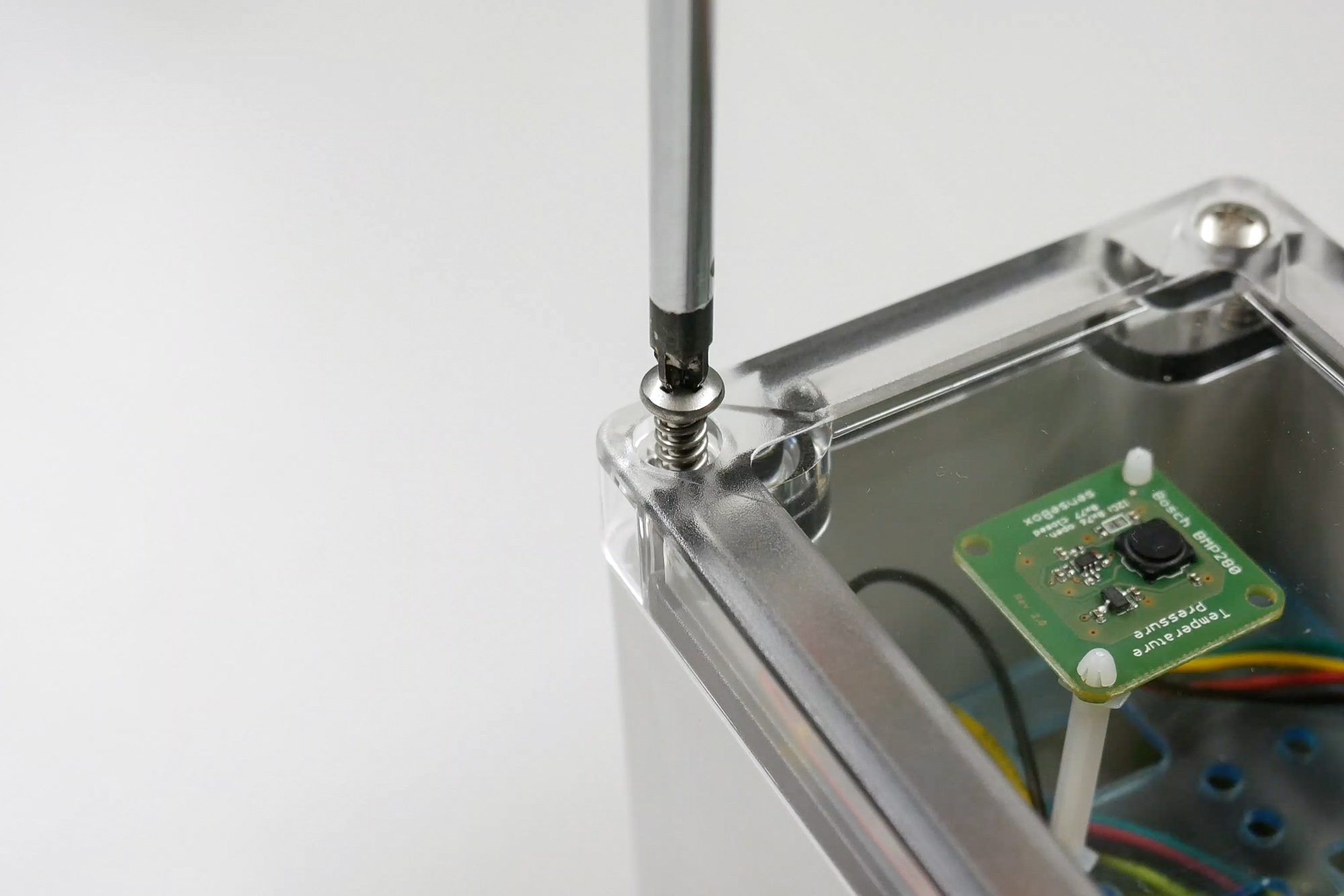
Now, screw in the quick-release fasteners to seal the senseBox.